After building a couple of test mould and deckles (that were smaller and used a variety of materials for the screen), I decided to build bigger ones that were more period to use at the AZ Ren Faire (1540-1590).
Some of the best research that I found was an PDF article from Hand Papermaking by Tim Moore. Tim Moore is an amazing Toolmaker that makes hand tools and many of them are for papermakers. He had the occasion to dissect old British moulds and deckles, so he is extremely knowledgeable about how papermaking moulds and deckles are built.
I don't have the time, twining loom (Tim Moore), or materials to build "laid" moulds (they make beautiful paper), so with my first period moulds I went with "wove" moulds. I had to determine what the period materials might be (wood, screen, fasteners, joint types, etc.) and check to see if the items were available.
The woods that were available then, water resistant and near (or accessible) to Europe started off to be a big list but were whittled down to just a few. Even though woods from Southeast Asia are probably the most water resistant, they were difficult to get then and really expensive now! I decided to use African Mahogany for the mould and Italian White Oak for the deckle. (Note: don't use White Oak. It is not as dimensionally stable as the Mahogany or something else). I was able to get the Mahogany in large dimensions (8/4 or about 2" thick).
I needed to decide what size paper I was making before I started cutting wood. A3 mould(s) with 3 deckles, 1-A3, an A3 divided into 2-A4's, and an A3 divided into 4-A5's. That is part of the beauty of using European sizes.
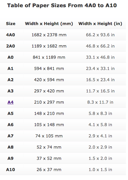
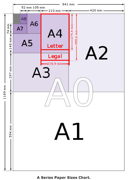
The size of the paper ends up being the size of the hole in the deckle. The deckle overlaps the mould/mould screen by 9/32" or 0.28125". Also depending on the method of corner jointing, you may have to add or subtract length to the mould size. So I started with A3 size (11.7" X 16.5") plus 9/32 x2 = 1/2" for the deckle overlap on both dimensions. This gave me an inside dimension of 12.2" (12 3/16 + a 1/64th) X 17". I used a finger or box joint on the corners (very strong, lots of surface area for gluing). You can pin the corner with a dowel but it is really not necessary. Test fit and remeasure. Don't put it together yet.
The Support Ribs
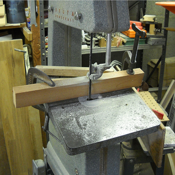
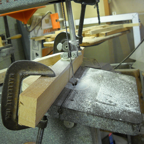
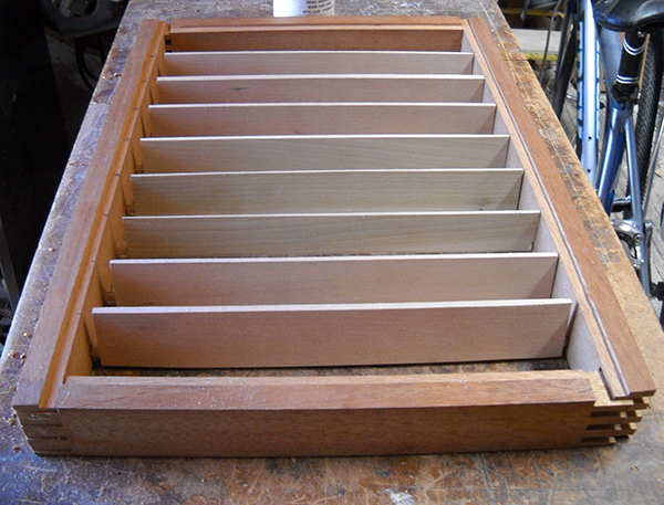
On the first moulds that I built I said to myself, "I don't need these ribs, the frame is plenty strong enough to support the screen and the paper." Which was true but… the sheets that were formed were impossible to "couch". There was nothing to help support the screen/paper in the transfer to the wet felts (and the felts were not wet enough either). The ribs (which I made out of Basswood) are shaped like a fin. Smaller at the top and wider at the bottom. It is secured to the side rail with a pin or dowel. You can carve the ribs to smooth fin with a carved pin (all out of one piece) or add the pin or pin them all the way through the rail after the mould is assembled. Theoretically, you should use 12 ribs in a mould that is A4 size. I couldn't fit 12 in a A3. I could only fit 8. I suppose if they were more dainty, it could happen
I cut the ribs out of Basswood on a band saw with an angle jig. I tried cutting smaller ones on the table saw but there is a lot of waste with the blade thickness. I cut the angles and then the length. Then bored the holes for the dowel pins in both ends.
Cutting the channel to mount the screens
The screens that I chose to use is a #6 mesh Stainless Steel support screen (yes, I know it is not period but it is also not seen), and a #30 mesh phosphorous-bronze screen (more period than the stainless). Some hand papermakers use a #40 mesh, which will drain slower. Since I am demonstrating the process, draining slower would be boring for the spectators watching. The channel will have to accommodate both screens. Some people add to the depth of the channel to accommodate the brass shims and brads used to secure the screens to the frame. Note: the depth of the middle part of the deckle should take care of the height of shims and brads.
You can cut this channel with a single pass of the table saw (or two if you need it deeper) or you can use a router or a chisel. I am not great with a router (scares me a bit) and I can chisel a straight line but depth is not well controlled. I make this channel the same width as the brass shim material.
Finish adding ribs, support dowels and tiny holes to sew screens on
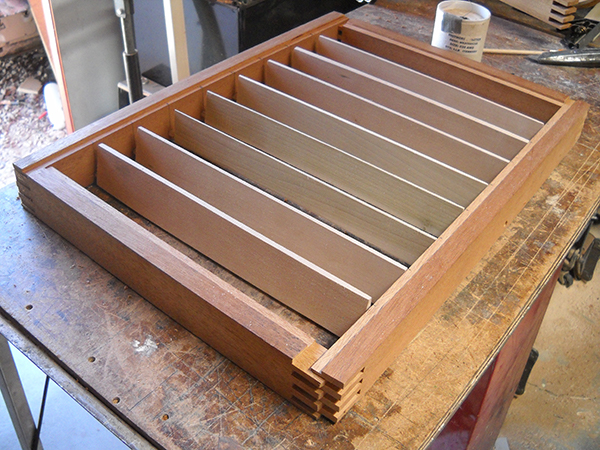
Each rib there needs to be mounted to the frame. Bore a hole in each side of the rib (in the same place) to insert a dowel. Then holes are drilled in the side rails to mount the ribs. You can round the bottom of the ribs to help with drainage (and it looks cool) but not absolutely necessary. Two additional things must be done to each of the ribs: To keep the screen(s) from flopping they must be tied to the ribs with very small diameter wire (brass for period). Small holes are drilled (the diameter of small wire used to tie on the screens) 1/16" down from the top of the rail (no more that 1/8") and about every inch along the rib. I built one without sewing the screens to the rails but the paper didn't couch very well. A dowel that runs the length of the mould that go through the end frames and all the ribs. This keeps the ribs upright and keeps them from turning if they come loose. The best way to do this is a horizontal borer or swing the table out of the way on your drill press and with a long drill bit (and patience) drill a hole from top to bottom through the rails and fins and insert a dowel (glued) through the series of holes. The images that follow are pre-assembly, so it is not glued yet and the length-wise dowel has not been drilled, inserted or glued. As you can see the top of the ribs should come right up to the bottom of the channel.
Assembly and Spar Varnish
After pre-assembly make any adjustments necessary before gluing. You are literally gluing the finger joints (or what ever joint you used) and ribs together at the same time. Use appropriate corner clamping methods with the addition of a clamp across the width to secure the ribs in place. Make sure that the ribs are all vertical. When all joints have dried, drill the holes for the lengthwise dowel and insert and glue. Let dry as well.
Tim Moore uses "Thompsons Water Seal" on his mould and deckles. I don't know enough about Thompsons but I didn't think I wanted to take the screens off to re-seal the wood. I used a spar varnish. It has a yellowing tint to it but it really doesn't affect how the mould and deckles work. It is an older product (spar urethane is similar but doesn't seem to be as hardy as spar varnish), sandable if needed and builds up nicely. I did 3 coats, with light sanding in-between. Here in the Arizona desert, it dried pretty fast. I have been using the mould & deckles for 3 1/2 years and there is only a little wear where I hold on to them and set them down. It would be an easy fix when it becomes necessary.
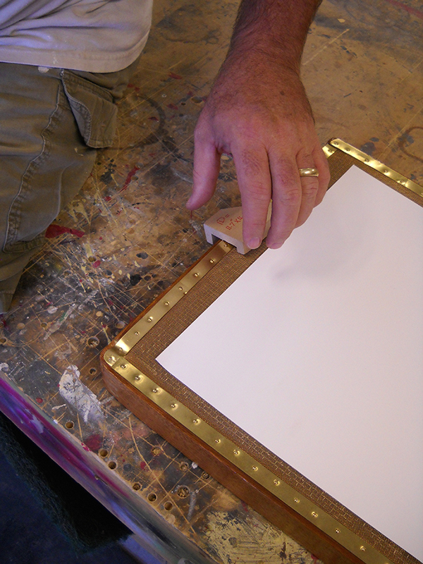
Mount and secure the screens (sewing and brass strips and brads)
First lay the #6 Stainless Screen on the top of the mould and mark (usually with masking tape) the outside edges of the screen channel. Cut the screen and lay it in the channel. Do the same with the #30 mesh. Flatten them (or put weight on them). Start on one end (short rails) and pin down with a brass shim and brass tacks (1/2" i think). Using pliers (or better yet canvas stretching pliers) carefully pull the screens in the opposite direction of the tacked down end. Add the brass shim and attach it with brass tacks. Do the same with the other edges, pulling and tacking. Using the small diameter wire secure the screen to the ribs.
Some people don't drill the screen securing holes in the ribs close to the top. They drill them farther down or not at all. It is difficult to sew the screens to the holes in the ribs when they are close to the screen. Some just tie the screens around the whole rib. As long as the tying doesn't come loose or trap paper pulp in any gaps. Tie the wires as tight as you can. The wires shouldn't distort the surface of the screen.
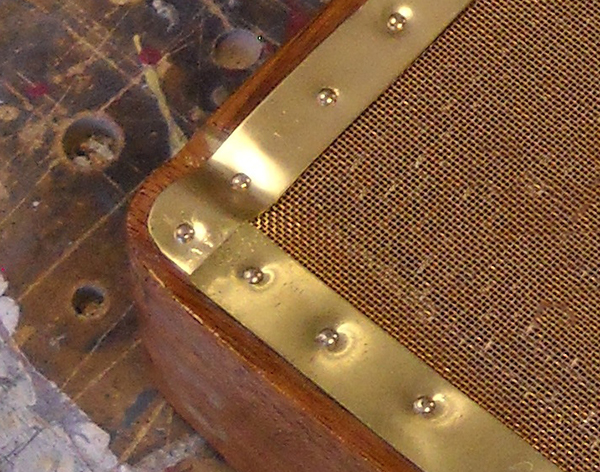
As you can see, the brass shim drops into the channel cut by the table saw. As this looks odd, it really doesn't affect the paper making process, due to the deckle coverage. You could solve this by cutting the channel a different way or adding a wooden block to that area.
Making the Deckles
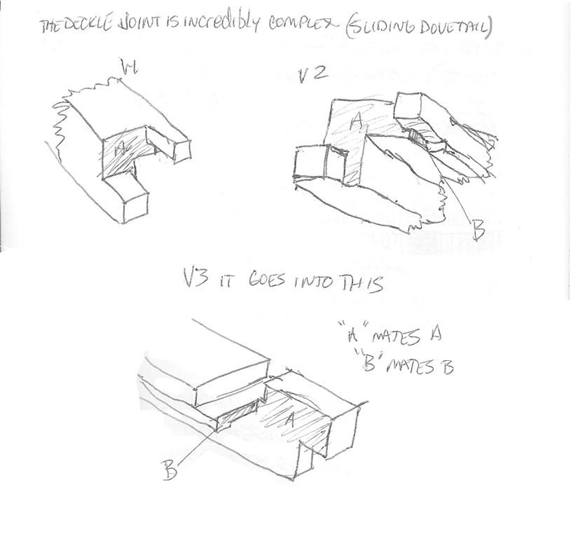
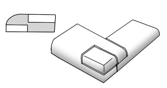
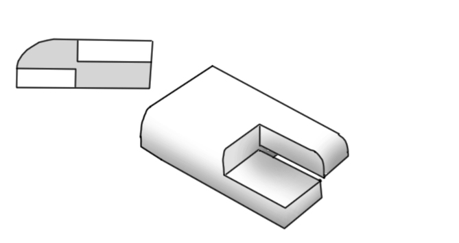
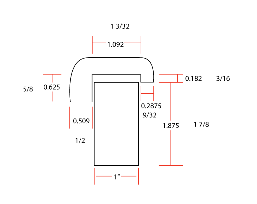
There is a real art to making deckles. The inside profile of the deckle directly affects the edge of the paper. It can be straight, chamfered, rounded, inset, and many other shapes. The truly important feature is that the deckle seals to the top screen, creating a dam that holds the pulp into shape until the water completely drains away. If it is not tight in an area, the water will drain faster and create a thinner sheet in that area. Uneven sheet forming. Below is a diagram of measurements for a deckle (adapted from Tim Moore) and a quick (but difficult) version.
There is a special "Deckle" corner joint that I have yet to figure out how to cut. I believe that it is called a "sliding dovetail". There is a flatter one that is "double lap" joint? Literally you can use what ever strong corner joint that you are comfortable making. I emphasize strong. If the corner is weak, it will change size and get weaker with use. Save your wits by making it as strong as possible.