Now all the pieces are done, how do they all fit together? What should I watch out for?
First: Make sure all the parts are dry and handy. If you haven't test fitted everything, do so now. Trim, extend, whatever you need to get everything to fit properly and tightly. This includes bedplate, backfall, drum and shaft, and drain plug. You have semi test fitted the backfall and bedplate, so you could get the right position of the mid-feather before fiberglassing started.
Second: Fit the bedplate and backfall in relation to the drum and shaft. Make sure that these are in the right position to the drum. I didn't talk much of the motor and mounting of the drum shaft on the drive arm. There is a drawing (Hollander Version 2.0 in The Tub section) that will give you an indication about size, position and mechanics. I thought, at first, I could build the drum arms out of wood. But I strongly discourage that idea. By the time I got to assembly, I had learned to weld well enough to build a metal frame out of 1 1/2" square steel tubing. The welder was a flux wire welder from Harbor Freight. Metal from Industrial Metal Supply. Relatively inexpensive. Or find an acquaintance that can weld it together. It is a rectangular frame with two door hinges welded to the back on the bottom, in such a way that they can be bolted to the bottom of the base board. The arm should be able to be lifted out of the way of the tub. The motor (a 1/2 hp, capacitor motor fitted with the proper pulley) is inline with the pulley that will be mounted to the shaft. The motor mounting bracket is a flat steel plate with elongated holes that allow the motor to be slide backward to create a tension on the belt.
The bearings are self-centering, greasible, pillow-block style bearings that are mounted on the top (or bottom, if you want) of the metal tube frame. Before solidly bolting them to the frame, test lift the arm to make sure the travel of the shaft moves withing the curved slots that were built into the tub. Once everything clears, bolt the bearings with the shaft and drum mounted. The height adjusters are the last thing to add to the arm.
The height adjuster(s) are just large all-thread rod with nuts welded to the frame, additional nuts to lock them in position. Additional two nuts per rod are added underneath to stop the arm from dropping too low. Find the height where the drum hits the bedplate and move it up slightly from there. Place the two nuts tight against the arm and use this as the absolutely lowest point. I also added crutch tips to the bottom of the rods to take some of the vibration out of the system.
Third: Now you can mount the backfall and the bedplate. With them still in position from the fitting, mark the mounting holes for the bedplate and draw around where the backfall should be positioned. Have someone hold the backfall or tape it in with duct tape and turn the tub and backfall on its side and drill pilot holes for the screws you are going to use to attach the backfall. You can add silicon caulking to the bottom of the backfall now before screwing or wait (or both). Reposition the backfall and screw it to the tub base from the bottom. Next drill holes for the bedplate that you marked previously. These are for the mounting bolts. Add a washer to each side. I used locknuts for the bottom of the bolts. Just in case. Before continuing, I silicon caulked the front, sides and rear of the bedplate and front, sides and rear. I didn't think this was necessary, at first. But unprocessed shred and fibers find their way into those nooks and crannies an can cause havoc on a great batch of pulp. They are invisible until you start sheet-forming. Many a batch as been ruined by unprocessed shred.
Fourth: The drain… this is an issue that I originally thought wasn't. Questions that came up were, 1) where is the best place to put the drain, 2) what do you use to create the drain, 3) how do you install it?
Well the best place to put it is in the eventual lowest spot. Near the end of the beating cycle, I lift the back (after the backfall, where the pulp makes the turn), so the pulp keeps moving. That makes the front (before the bedplate/drum) the lowest and best place for the drain.
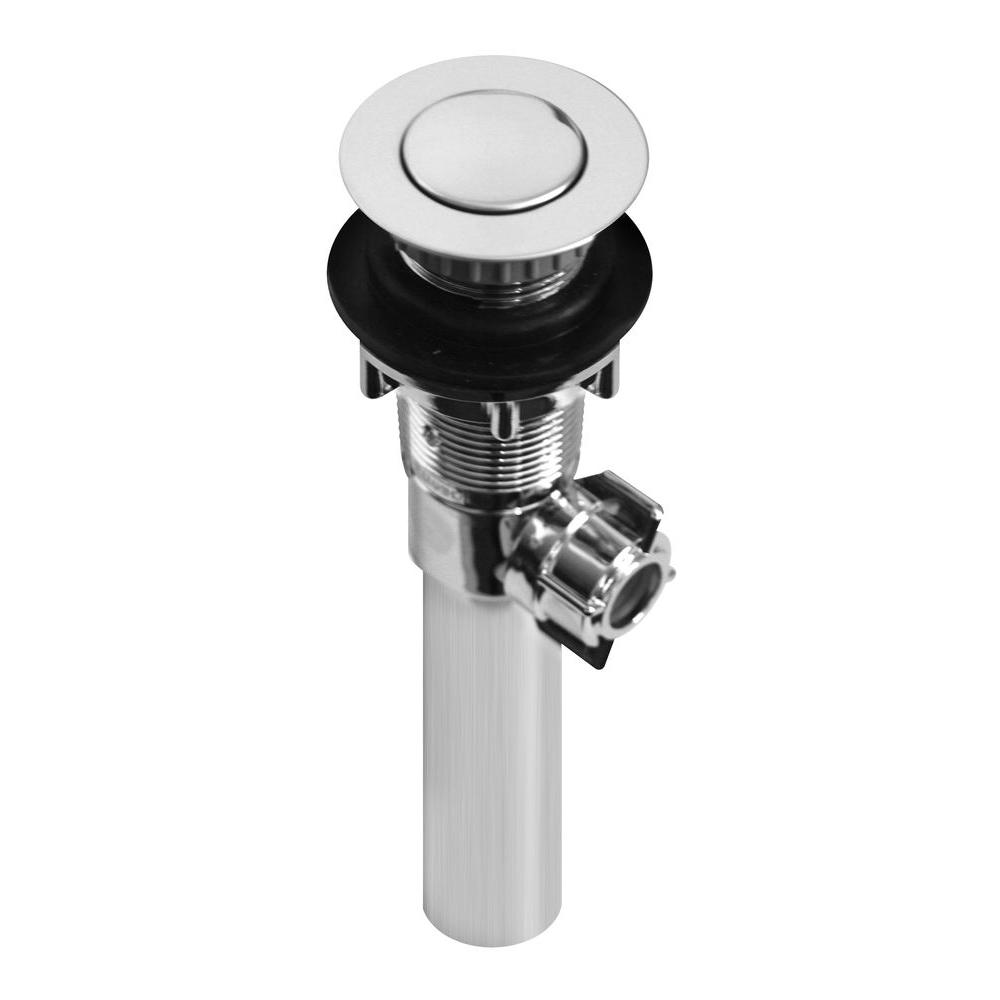
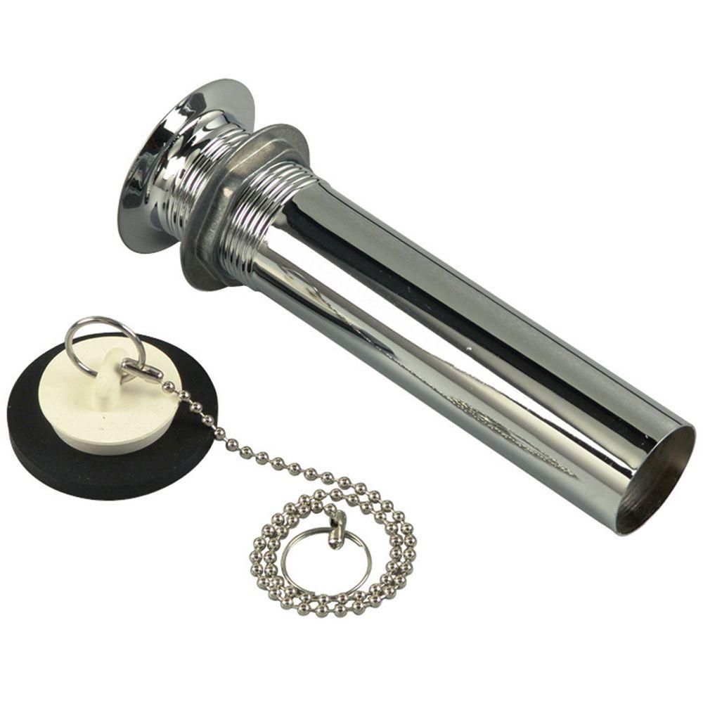 You don't want the drain to stick up very high (like mine). It could imped the flow of the pulp (like mine). Too low or have a depression in the drain hole, it will catch pulp (or worse the early shred and create a mess later). I used a short as possible 1" PVC threaded tube with rubber gaskets to create the drain. Then screwed a cap on the top. It really sticks up too much and changes the flow into the bedplate/drum. You might be able to put in a regular type drain with a plug in it or a fancy pop-up tub drain (if it seals really well). Either way, you have to drill a large hole in the bottom of your tub to facilitate the drain. Which ever you pick, seal it tightly so it doesn't leak. You will have enough leaks, you don't need another.
Fifth: Mount the arm, motor, drum, shaft, and bearings to the base. Since you figured out the pulley ratio in Hollander Beater Math mount the larger pulley to the drum shaft. Now you can figure out the size of belt you need (if you haven't done that previously).
Optional: You might want to obtain or build some type of speed control. There is never such a load on the motor that it heats up greatly, but to have some way to control how much power is going to the motor and a way to shut it off quickly would be an advantage. Accidents can happen. You don't want something going through the beater that is not fiber/shred. Like your hair getting caught or heaven-for-bid your shirt or hand. The beater is a vicious machine that must be respected. I don't have a guard on the pulley/belt/motor system. I am rarely on that side but I should. My neighbor, Phil, who is interested in the stuff I build, brought over this antique rheostat that has an off/on switch and a dial that supplies power to the motor. 0-100 and then it also goes 100-180 to overpower the motor. I run it at about 70-90 most of the time and finish it off at 100. I only go over if it sound like it is laboring, and then not for long. Not very good for the motor. The on/off switch is the best feature. If the Hollander binds, I can immediately stop it, preventing it from tearing itself apart. There are speed controls out in the world that range from $30 to $300. You might be able to build one (instructables), but shy aways from anything that uses a lighting dimmer switch. LED dimmer switches are better but still very bad for motors.